Shear strength of earthbag wall with weak cohesive fill
Patricia Stouter, August 2011
Earthbag is a growing sustainable building technique that is increasingly desired in the developing world because it costs only a quarter as much as concrete block walls, is easy to learn, and does not require power tools. Because other geo-textiles perform well in hazardous areas, earthbag is desired in seismic risk areas. But structural testing is needed to determine safe plan and construction guidelines for different levels of risk.
Earthbag is usually built with cohesive earthen fill. Because it is often designed to fulfill adobe building standards, earthbag can be compared to adobe test and standards values to provide safe guidelines for use in the developing world. But to date almost all research by engineers has been limited to the structural performance of atypical sand-filled bag walls.
To explore the shear strength of a weak cohesive fill, a plastered earthbag wall portion was subjected to static diagonal compression.

The earthen- and lime-plastered test wall was still stable after surpassing peak strength. With no reinforcing mesh, its peak shear strength was superior to most sand bag walls tested, and comparable to one with cement stucco reinforced with chicken wire. More rigorous testing of both weak and strong cohesive fills in earthbags is merited.
INTRODUCTION
Earthbag building is a sustainable hybrid earth technology using non-biodegradable bags or tubes as formwork for cohesive, moist earthen fill. A conventional earthbag is filled with a cohesive soil mix that becomes firm when tamped and cured. It becomes a type of un-fired earthen masonry unit, similar to adobe.
Earthbag actually comprises a family of geo-textile materials. Mesh tubing, fibrous fill, and sand or gravel fill are different options. Base or plinth layers of sand or rounded gravel bags may also be able to serve as simple vibration dampening or base isolation devices. But 90% of the earthbag building around the world uses only cohesive soil fills in solid fabric for strength and ease of construction.
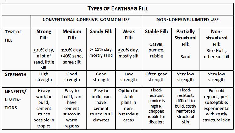
Soil fill is chosen and modified to fit very specific conditions and needs. Soil fills influence strength, construction difficulty, wall cost, and usefulness. Cement stucco works best with sandy fills while lime plaster matches the expansion and drying needs of clay-rich fills in most climates. But the potentially strongest wall assemblies of the conventional construction techniques should be explored first.
RESEARCH PRECEDENTS
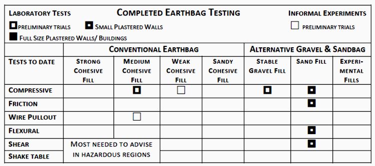
Unfortunately, to date testing has mostly been done on atypical sand fills, as shown below. Sands are less variable than soils, simpler to analyze and repeat tests. Unlike cohesive soils, they require little curing time before testing. Filled bags can be reused for the next test. But because sandbags tend to slump and do not grip barbed wire well, they often in practice require significant amounts of cement that raise costs in thick walls.
The only study of a full-sized, plastered earthbag building portion to date is a U-shaped wall completed at the Cape Peninsula University of Technology1 in South Africa for Dr. Johnny Anderton of Eternally Solar.2 With a chicken wire reinforced cement stucco surface this sandbag wall proved strong enough for moderate wind conditions in a region without seismic risk. This wall system uses channelized sewn bags without barbed wire or vertical rebar that reduces labor. It is well suited to remote sites or locations where metal may corrode, such as near coasts, volcanoes, or industrial centers. It uses approximately 45% more bags per wall because courses are thinner.
The CPUT test was primarily for flexural strength, and showed a peak strength of 44 psf/ 2.1 kPa. The peak strength of the return walls in shear may not be truly representative, but appeared to be 23 psf/ 1.1 kPa. This bag system should be also tested with cohesive earthen fill in a straight wall portion, with and without added barbed wire to compare to standard earthbag strengths.
A test at the University of Florida used air motion to test an un-plastered sandbag wall. Preliminary results show the structure did not become unstable when loaded with 60 psf/ 2.9 kPa.
The most complete studies to date of bag walls are by three different graduate students at Bath University. Their small bags created walls approximately 80% the width of a conventional earthbag wall.4 Chris Croft reported on his and earlier tests of flexural and shear strength of these sand bags.
Test results showed that earthbag walls with barbed wire can sustain considerable deformation without collapse. Croft’s work also showed that plaster covering both sides of the wall increased strength of the wall assembly significantly. When cement stucco was used, the peak shear strength (without barbed wire) was about 119 psf/ 5.7 kPa or 180 psf/ 8.6 kPa with chicken wire.
How do these tested strengths of sand-filled bags compare to other earthen building materials?
COMPARING EARTHBAG TO ADOBE
Earthbag builders have successfully used adobe guidelines in non-hazardous regions for decades. Like adobe, bag walls have enough compressive strength for modest buildings and gain stability from wall thickness. Although flexural strength for adobe walls is low, traditional adobe codes strengthened walls by keeping distances between bracing 6m or less and walls to 6 or 8 times as high as thick.
Earthbag walls are slightly thicker than some adobe walls, 15” thick/ 38 cm compared to adobe at either 11”/ 28 cm or 14”/ 35 cm thick. Earthbag walls weigh more per length than the thinner adobe walls, and for structural purposes should be compared to thicker adobe.
Earthbags have greater potential tensile strength and flexibility than unreinforced adobe walls from their matrix of barbed wire and poly fabric. With adobe-type soil fills, bag walls may have greater strength than adobe because of the tamping process during construction. But earthbag units also can use a wider range of soils, because each earthbag is protected by the confining bag surface and mandatory plaster. More should be learned about fitting soil fill to the level of hazard at the site.
ADOBE RESEARCH AND STANDARDS
Engineered standards for earthen buildings based on structural testing of adobe and rammed earth were created in 1998 in New Zealand.6 The non-engineered guidelines for adobe appear to rely more on tested shear strength than on flexural or out-of-plane strength.
The New Zealand Standards include a valuable guideline for non-engineered buildings7, assuming ‘standard grade’ quality for adobe. Those who cannot afford custom engineering or complex materials testing have a means of checking that their building has enough bracing for low, medium or high seismic risk regions. The design shear strength values assumed for standard grade materials are conservative.
This code only allows unreinforced adobe walls in low seismic hazard areas. Guidelines for reinforced adobe required in high seismic risk areas rely on vertical steel rebar and horizontal plastic geo-grid inside un-plastered walls.9 This type of intensive reinforcement (possibly combined with stronger ‘special grade’ earth blocks) has resulted in some high shear test values,10 but creates a limited ductile response.
New data after several earthquakes in New Zealand affirmed these strength standards for adobe.11 A magnitude 7.1 earthquake caused 0.7- 0.8 peak ground acceleration at the site of one reinforced adobe house with 28 cm thick walls. Very limited damage resulted despite significant shaking. For ten modern earthen houses of adobe and other earth techniques, reinforcement and design conforming to the standards resulted in only minor damage due to differential ground movement or excessively high walls.
Evidence reviewed in the same paper also showed that some adobe without code level reinforcement survived severe vibration well. One historic earthen cottage with a ground floor of unreinforced 20”/ 50 cm thick adobe received a lower magnitude but very shallow earthquake that caused peak ground acceleration levels as high as 2.2. Although the earthen walls supported an upper story of timber framing, they still received only relatively minor and repairable cracking within walls.
Engineers at the Catholic University of Peru have sought less expensive ways to reinforce existing adobe, since steel rebar is costly and must be installed in new walls. They have tied interior and exterior geo-grid layers together through holes drilled in existing adobe walls, and plastered with earth.
This retrofit system preserves the ductile performance of adobe. Shake table tests of ¾ scale buildings have survived horizontal motion up to 1.2 g without collapse. Their test (marked APM on the following chart) registered a peak strength of 40 kPa, more than twice as high as simple plastered adobe (AP). Plaster and mesh reinforcement increase shear strength dramatically.
Many of the researchers tested primarily for lower serviceability limits. In the developed world builders prefer to use standards that will prevent the need for re-plastering with gypsum materials that require high skills after a wall deforms more than 1/250 of its height.
In contrast, this comparison focuses on higher peak strengths from the same reports. Peak strength is the most force a wall can resist. When the mortar joints of an adobe wall crack enough to allow the center of gravity of the wall to move 1/2 or 2/3 of the wall thickness, most become unbalanced and overturn or collapse. In the developing world preventing wall collapse may be more important than preventing plaster damage. Earthen or lime plasters are repairable. Plaster that cracks during vibrations can also protect underlying walls.
Does earthbag have enough strength to weather earthquakes like adobe?
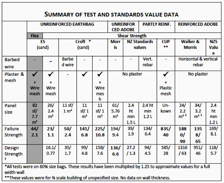
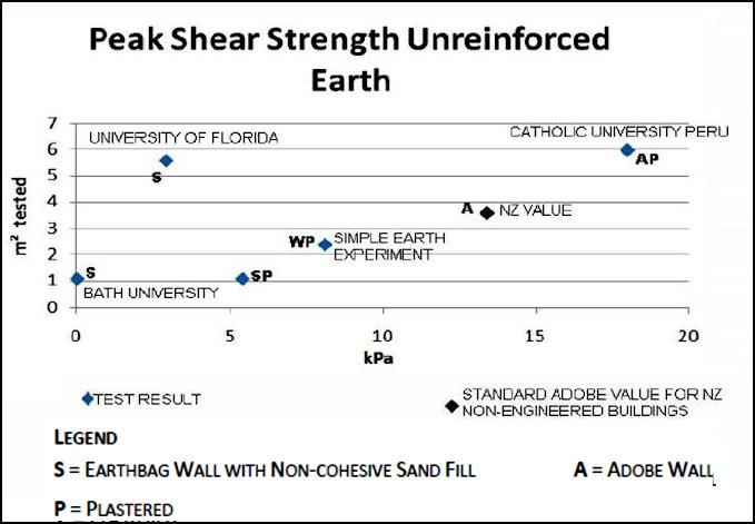
The chart that follows compares the peak strength of test results and standards values in pressure versus test wall size. Although peak values are given for both adobe and earthbag, the effects on these test walls are different. Unreinforced adobe walls are usually unstable after peak strength. Adobe reinforced with either plaster and mesh or internal rebar remain standing even though deformed. Tested earthbag walls with only barbed wire also remained standing and mostly stable although deformed..
Most tests were completed with dynamic cyclic horizontal pressure on tops of wall portions. Only the CUP test reflects shake table performance of an entire building (for this one record m² tested is an approximate figure for the wall length that does not reflect total area of building walls).
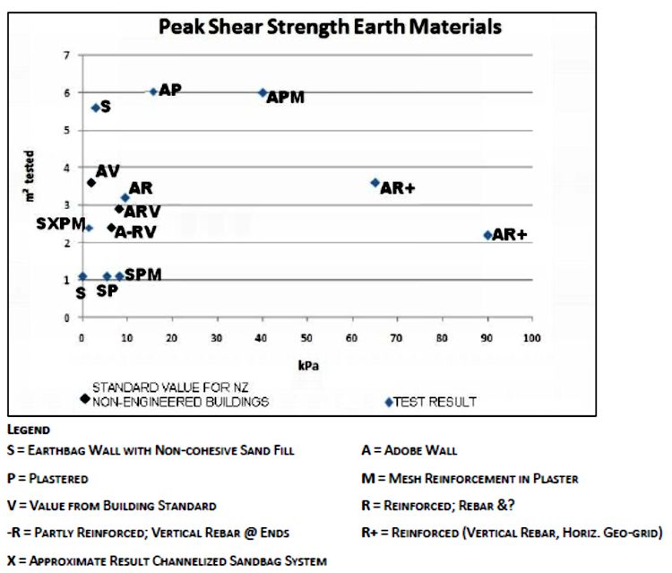
Peak strength shear values from tests of sand bag walls so far have not approached the high shear values seen in plastered adobe with plastic mesh or in steel reinforced adobe. They have been near or below the conservative standard grade shear strengths assumed by NZ for non-engineered buildings. With cement stucco and chicken wire sandbags approach the strength assumed for unreinforced adobe.
Can earthbag with cohesive fill approach or surpass the strength of plastered and geo-grid strengthened or heavily steel-reinforced adobe?
Note: All designers use factors of safety to insure that there is a margin of error to prevent damage to buildings. The NZS committee recommends a design factor at 70% of the failure value for reinforced walls. Test failure values and design strengths were adjusted by this proportion to provide fair comparisons.
MATERIALS
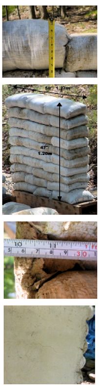
To begin to answer these questions, the author built a 4’ x 4’/ 1.2 x 1.2 m height earthbag wall panel in May 2011. In late July it was subjected to a simple form of diagonal compression.
 This test used a low-strength cohesive soil as fill to establish a lower boundary for unreinforced earthbag wall shear strength. Builders using cob and adobe recommend minimal silt in building materials,13 and engineers assume that silt is 1/3 as strong as a mixed sandy-silty clay.14 But acceptable parameters for successful earthbag building are not yet known.
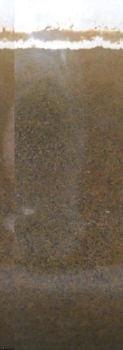
The soil used was mostly a material called silt by a local gravel yard, with about 20% by volume of a moderate strength clay added. The clay contained both fine and very coarse sand with some very fine gravel. The traditional earthbag builder sediment test15 revealed a profile of more than half silt, and less than 10% clay. A soil sample has been retained for more accurate analysis.
Right: View of settled soil sample
Preliminary bag tests confirmed that the tamped, cured fill became firm and held a 3” nail securely. This fill created a stable wall, but individual units had lower strength than required for adobe. Unlike informal tests for adobe strength, when dropped from 3’ (90 cm) height some earthbag units with this fill broke in two pieces or lost portions larger than 4” (10 cm).
Bags used were standard, new woven solid poly fabric 18 x 30 inches (46 x 76 cm) which produced a conventional 15 inch/ 38 cm thick wall. Two strands of low-tensile strength galvanized barbed wire were used between each course.
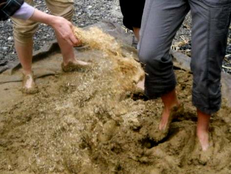 A clay-rich earthen plaster with manure for fiber was applied as a base coat to fill the characteristic nooks between bag courses. One side was finished with a finer earthen plaster containing chopped straw. The other side received a standard lime plaster in one coat with a small proportion of chopped straw.
Right: Trampling chopped straw into finish plaster
PROCEDURE
WALL CONSTRUCTION
A 5’-6”/ 1.7 m long wooden base was constructed of pressure treated Douglas fir assembled with galvanized deck screws. 2×8/ 50×200 lumbers formed the sides and 2x12s/ 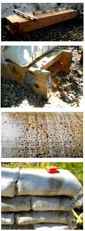 50×300 formed the top and bottom plates. 4 pieces of blocking were included inside to support the wall weight. Galvanized metal nailer plates were added above the axle holes and at the ends of the boards for reinforcement.
Right: wooden base
Right below: Metal plates at axle location
This base was placed on the gravel of a firmly compacted parking area and leveled.
The first course of doubled gravel bags was placed down onto nails sticking up from the base. This course was 58”/ 1.47 m long. Additional nails were hammered in at each end of the gravel bags. The gravel bag course was tamped lightly. A second layer of bags contained very coarse sand. This measured 50” long and was tamped firmly.
The earthen fill was mixed by inter-layering silt with dry clay crumbled by hand into 1”/ 2 cm or smaller pieces. Soil was hand mixed in wheelbarrow loads, and moistened enough to break into 2 or 3 pieces as 1.5”/ 4 cm balls dropped from 5’/ 1.5 m height.
Right: Weeper bag
Because of the high silt content, soil moisture content was hard to regulate perfectly. No drier batches of mix were used, but many batches were damp enough to cause ‘weeper’ bags. These bags ooze moisture as tamped. It is noted in Earthbag Building17 that these types of bags with clay fill cure stronger than drier bags. With a silty fill these bags are too bouncy to compact under tamping unless dried for a day first. The damper silty bags were not obviously stronger.
 Building short earthbag wall portions is more complicated than longer walls. Bags at each end of the wall must be pre-tamped well during filling. Small end bags should be at least 12” long/ 30 cm.
Although running bond bag overlap is considered best at 8”/ 20 cm or longer, it is difficult to make 24”/ 60 cm long bag units with the common 29 or 30” long bags. Custom longer bags may be helpful or a longer test wall length. On this 4’2”/ 1.27 m long wall, running bond overlap ended up as small as 4”/ 10 cm on many courses.
During tamping each bag course reduced in size from 7” to 5”/ 18 to 12.5 cm and became firm. Bag courses also keyed into the course below and settled around the wire barbs during tamping.
Right above: Before and after tamping
Right: Finished test wall
10 courses total of bags were placed, with sides and ends plumb. .
The wall was covered with a tarp in rainy weather. After 2 days the sides of the wall were tamped with a mallet to flatten the wall surface. When the upper course was tamped an adult sat on the bag layers to prevent wall shaking and bag movement.
Within a week earthen infill plaster was placed in the nooks between courses on both sides of the wall. The plaster was applied to the bags when the bag fill had become firm but was not completely dried.
This plaster consisted of moderate strength clay with a small amount of added sand and manure. Several days later a single coat of lime plaster was added to one side and an earthen finish coat on the other. The lime plaster was 1 part lime putty to 3 parts sand with added chopped straw. Thickness of finish layers varied from 0.50- 1 inch/ 1.5- 2.5 cm.
Bags were left exposed at the ends of the wall.
Right above: Lime and earthen plaster side view
Right: Lime plaster condition when cured
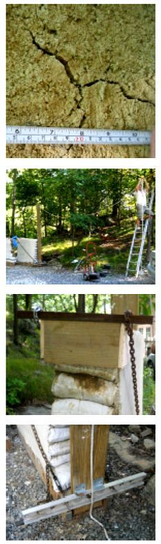
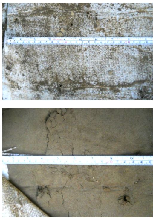
These finish surfaces were kept covered with a tarp and sprayed lightly with wat er twice a day during curing. After two months of curing the finish plaster coats were well dried. The lime plaster dried with 4 minor non-structural cracks less than 1/8 inch/ 3 mm wide. The longest crack was 10”/ 26 cm long. The earthen plaster had more cracks and wider, some up to a quarter inch/ 6 mm across. All the earthen plaster was well anchored to the wall, and fibers were visible spanning the cracks and uniting the plaster.
Testing occurred 2 months after plastering. At the time of testing the lime plaster and most of the finish earthen plaster was dry. Because of leaking through the tarp covering the wall portion, the earthen finish plaster at the upper corner where the diagonal pressure was applied was damp.
Right top: Earthen plaster crack close-up
Below: Earthen plaster condition at time of testing
TESTING EQUIPMENT
An upper corner bracket was attached by chains to a lever arm on the opposite side base. The far end of the lever arm was attached to a rope that led through a single pulley to a support for weights.
Right top: Overall view of testing
Right: Corner bracket
The plywood corner bracket was capped by a piece of angle iron. Chains looped over and ran down to turnbuckles.
The lever arm was a single 2×10/ 50×250 of pressure treated Southern Yellow pine. Metal brackets were screwed to the wood to seat the lever arm in place on a pivot point formed by an axle of metal pipe. The turnbuckles were attached to a strong piece of aluminum channel bolted to the other side of the lever. The turnbuckles ran through eye-bolts held in place with large washers.
The chain was attached to the lever arm 5”/ 13 cm above the center of the axle on which it rotated. A rope was tied to the other end of the lever arm exactly 113”/ 2.87 m from the axle. This produced a mechanical advantage of 22.6 to 1.
 Right top: The laser dot at the beginning of testing
A strong nylon was used for the rope from the lever arm to a pulley suspended by ropes in line with the wall. Force was applied to the lever arm by placing gym weights on a shelf of wood and metal strapping.
A vertical line was marked on the finished plaster surface in pen from the top of the wall to the bottom. At the level of the second course from the top a thin plastic metric ruler was taped and nailed to the plaster with brads. A contractor’s laser level located 4’/ 1.2 m distant was aimed at the ruler.
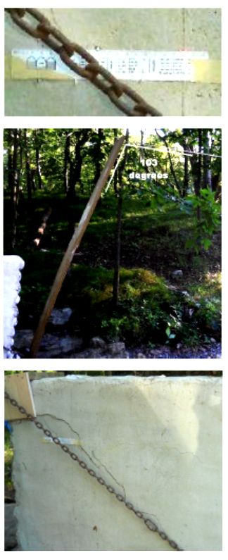
Right: Lever arm and rope angle
TEST
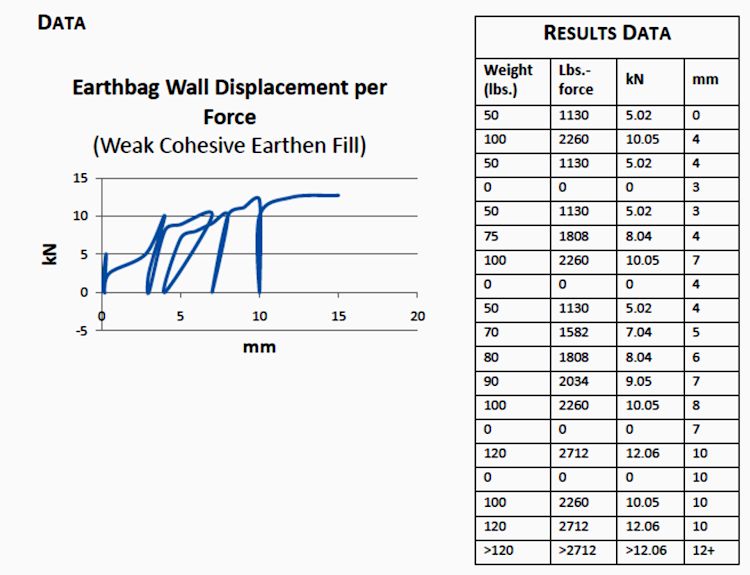
Weights were applied, left in place for 2- 3 minutes, and then removed, in gradually increasing increments. Measurements were noted and photographs taken after each increase.
When the first 50 pound/ 23 kg weight was first applied, the rope stretched. The weight was removed and the support shelf raised higher from the ground.
Three times the wall withstood the force applied by 100 lbs./ 46 kg with only 0.3 inch/ 8 mm displacement and little plaster cracking. The lever arm formed an angle between 90 and 103 degrees with the rope during tests.
Right: Cracking after 2nd application of 100 lbs.
After the first two applications of 100 lbs./ 46 kg weight (2260 lbs.-force or 10 kN) the wall flexed back to 0.1 or 0.16 inches/ 3 or 4 mm displacement.
During the course of testing the very thin cracks first noted in the lime plaster spread. By the third application of 100 lb./ 46 kg weights cracks had nearly joined and stretched from the upper corner bracket down to within about 24 inches/ 60 cm of the base of the wall near the chain.
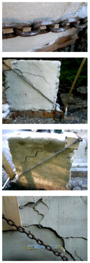
The chain rubbed on the plaster for several inches near the bottom corner of the wall. No cracks appeared in this region.
Right: Friction between chain links and plaster
After the third application of 100 lbs./ 46 kg weight (2260 lbs.-force/ 10 kN) the wall remained at 0.3 inches/ 8 mm displacement. Turnbuckles were turned and chain links removed to lessen slack in the chain.
At 120 lbs./ 54 kg weight (2712 lbs.-force/ 12 kN) the wall top moved a total of 0.4 inches/ 10 mm and did not recover when the weight was removed. Each time when more than 120 lbs./ 54 kg was placed on the weight shelf, the wall top moved enough to cause the shelf to bottom out.
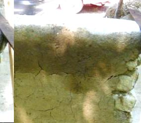
At this force a second major crack developed in the lime plaster above the level of the chain. On the earthen plaster side the most severe cracking was above the chains and obviously stair-stepped.
Right above: Lime plaster after 3rd try of 100 lbs./ 46 kg
Right: Earthen plaster after 3rd try of 100 lbs./ 46 kg
Peak strength may have been slightly more but a small enough increment was not used to be accurately measured.
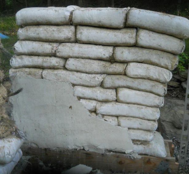
After 4 repetitions of more than 120 lbs./ 54 kg weight, the upper plaster was still firmly adhered to the bag wall. Although there were large cracks and some plaster surfaces overlapped, no plaster fell off the wall.
Right bottom: Final condition of lime plaster
The upper plaster was next removed to allow clear view of the relative motion of the underlying bags.
RESULTS
 The earthbag wall portion displayed some elasticity until peak strength was reached.
After three applications of more than 120 lbs./ 54 kg of weight, the upper courses of bags shifted horizontally a total of 10 inches/ 25 cm. Unlike the Bath University tests on sand-filled bags, the bags did not move apart during the test.
The wall end far from the applied pressure also compressed about 2 inches/ 5 cm, 4% of its height.
Left top: Bag wall with plaster removed
The earthbag wall was not significantly less stable than before the test. Out of plane pressure by hand did not seem to flex the wall more easily than before testing.
 Right top: Barbed wire openings
The most significant mechanism causing horizontal wall deformation was evident when the upper two courses of bags were examined. The poly bag fabric was slit only slightly at the barbed wire entry points. The contents of the bags were still in firm blocks.
But when the fabric was removed from two bags in the second course to examine the earthen fill, each wire barb had flaked loose a conical portion of the bag fill material. Some slight cracking in the surface layers was visible between the barb attachment points also. The surface of the earthen unit distant from the barb attachment points was firm and undisturbed.
Right: Bag fill loosened at barbed wire points
CONCLUSIONS
Despite the use of very simple testing equipment, this small experiment produced some new data.
Peak loading on this 15 sf/ 1.4 m² panel of plastered earthbag under static loading was about 2700 lbs./ 12 kN. Considering the panel size, it resisted 175 psf/ 8.4 kPa. Silty soil bag fill with barbed wire but no reinforcing mesh is very close to the 8.6 kPa value of the sandbags with cement stucco and chicken wire.
More testing with superior measurement systems is needed to evaluate how close this preliminary experiment comes to a valid indication of the shear strength of earthbag walls. This informal static trial of a weak cohesive soil earthbag panel may not be exactly comparable to the dynamic sand bag or adobe tests. Dynamic testing would be preferable since it often returns values higher than those measured in static testing, and may more closely approximate seismic performance.
This earthbag wall was purposely built of low-strength materials, to determine if ordinary earthbag walls built without special fill could be as strong as unreinforced adobe. This wall did not contain the vertical rebar that is usually inserted near openings in earthbag, which should also raise strength values when used in strong cohesive soil fills.
How does earthbag compare to the required and tested strengths of adobe?
Shear strength for earthbag depends on the bonds that can transmit the tensile strength of barbed wire to the earth units and their surrounding fabric. Strong clay fills, like those used in adobe, when tamped become strong enough that barbed wire barbs will bend back rather than gouge or flake the bag fill under stress.
Alternative reinforcements include small chunks of mortar added to barbed wire at depressions notched between bags, returning barbed wire to higher courses at openings, and the addition of some simple wire mesh pins.
Earthbag is inexpensive, easier to learn to build than adobe, and is already used in a wider range of climates than adobe. But most importantly, it deforms without collapsing under severe stress, offering the potential to save lives even if buildings are damaged.
If this hybrid earthen, poly, and wire material is strong enough for moderate seismic risk zones without a lot of added rebar and cement, it will be a great service to those rebuilding after disasters. Its flexibility could possibly make earthbag the best way to build cheaply and sustainably in high seismic risk zones.


