Hemispherical Dome Projection
This is an HTML version of Spherical Mirror: A New Approach to Hemispherical Dome Projection (2005). Paul Bourke is one of the top experts in his field, having written multiple papers, from research work. In addition, he has explained advanced concepts in easy-to-understand language and provided methods by which the average person can do dome projection.
By Paul Bourke, Swinburne University, Melbourne, Australia
Abstract
Planetariums and smaller personal domes can provide an immersive environment for science education, virtual reality, and entertainment. Digital projection into domes, called “full dome projection”, can be a technically challenging and expensive exercise, particularly for installations with modest budgets. An alternative full dome digital projection system is presented here that is based upon a single projector and a spherical mirror to scatter the light onto the dome surface. The approach offers many advantages over the fisheye lens alternatives, results in a similar quality, but at a fraction of the cost.
Introduction
Historically dome environments have been restricted to large planetariums and used primarily for public education in astronomy, illustrating the positions/motion of planets, stars, and constellations. These planetariums have used a variety of specialised projection hardware such as star projectors [1], laser projectors, and multiple edge-blended slide projectors. If the planetarium had the ability to present real-time digital graphics, the graphics were limited to a small portion of the dome, typically using a single CRT projector. Even though planetariums have been limited by the available technology, the immersive possibilities have been obvious, mostly due to two characteristics of the hemispherical surface: the viewers’ peripheral vision is engaged, and proceedings were conducted in the dark where there are often no frames of reference other than the projected imagery. The former is responsible for the vertigo one often experiences with rapidly rotating imagery; the later allows the apparent shape of the dome to be changed and is also credited with depth perception similar to stereoscopic 3D effects.
In more recent times planetariums have been upgraded to provide full dome digital projection, that is, a movie is seamlessly projected onto the dome surface at typically 30 frames per second. For larger planetariums this full dome projection is achieved with multiple projectors, most commonly CRT projectors. The projectors are carefully aligned and edge blended across overlapping projection regions. The system is driven by movies made up of fisheye images, these are usually diced into pieces and played back using specialised graphics hardware. Even more recently, high-end graphics systems have been able to project interactive graphics in real-time so it is no longer necessary to limit the content to movies. The content is not even limited to astronomy or even to science education, but indeed to any subject matter including, but not limited to, a wider range of educational topics, immersive spatial environments, virtual heritage, and even pure entertainment.
With the success of digital projection in large planetariums and the development of formal standards [2], interest has been growing in how to offer the same experience in smaller domes. These smaller domes are typically around 10m in diameter (found in many science centers) down to the smaller 5m diameter inflatable domes [3] that can be installed almost anywhere. The difference between these smaller domes and the large planetariums is largely in the system cost they can sustain. Not only do multiple projector systems have a high initial cost, they also have higher requirements in local expertise, and incur a significant cost of ownership. The solution to these cost problems has been to employ a fisheye lens attached generally to a single commodity data projector. The projector and lens are located in the center of the dome; fisheye frames from movies or generated by real time interactive applications are projected through the lens, and if created correctly they look undistorted on the dome. Such solutions have the benefit of being easy to manage and don’t usually require specialised computer hardware. There are issues such as resolution and brightness, but they are largely a reflection of the price one is prepared to pay for the projector. However for small operations based around public education or research based virtual environments, the cost of a good fisheye projection system may still be prohibitive. The alternative projection system introduced here significantly reduces the cost of dome projection while maintaining a similar quality and even offers some interesting advantages over fisheye projection.
Spherical mirror projection
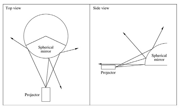
Figure 1. Representative rays off a projection source and reflected from a spherical surface. All illustrations are by the author.
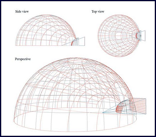
Figure 2. Typical position of the projector (16:9), mirror, and dome in a planetarium environment. Red lines illustrate the projected distribution of a regular grid.
The projection system proposed here uses a spherical mirror instead of a fisheye lens to distribute light in a wide solid angle. It can be readily appreciated that a spherical mirror can reflect light from a rectilinear frustum (produced by a commodity data projector) over almost the whole surface of a dome (see figure 1). There are a number of options for the projector/mirror placement in relation to the dome, but the geometry discussed here will consider a single projector within a small dome. In this case the spherical mirror is placed as close as possible to the rim of the dome (see figure 2). A number of alternative geometries and environments have been proposed in the past, for example “Ensphered Vision” that uses a convex mirror to project into cylindrical environments [4] as well as polyhedral spaces. The author has additionally explored dual mirrors/projectors located in the middle of the dome [5] with a single edge blend across the middle. Another
installation by the author located a mirror at the base of a vertically mounted truncated dome [6]. There are a number of comparisons one can make between a spherical mirror reflection arrangement and a fisheye lens system:
1. It can be advantageous to locate the projection hardware away from the center of the dome since the center is generally the best location for undistorted viewing. This is the classic problem for single-person domes with fisheye lens projection; the viewer and fisheye lens cannot occupy the same space.
2. The projector and optics have been separated, making it possible to choose projectors based upon the characteristics important for the application at hand, for example: price, brightness, resolution, or contrast ratio. Fisheye lens can typically only fitted to a very narrow range of projectors.
3. The coverage on the dome can be controlled by varying the distance between the mirror and the projector or by varying
the projector zoom. While it is true that the whole dome surface cannot be totally covered, it is equally not common for fisheye projection to cover the whole dome for pixel efficiency reasons [4].
4. The system is scalable to multiple projectors and mirrors in order to achieve higher resolution and complete dome projection. For example, a dual mirror and projector arrangement would give a single edge blend across the middle of the dome [5].
5. Unlike a fisheye projector located in the center of the dome, the path length from the projector to the dome is not constant, resulting in an intensity variation. Fortunately this is straightforward to compute and correct for.
6. Unlike fisheye projection, where not all the available pixels in the typically rectangular aspect ratio of the projector are used, all the pixels can be used in spherical mirror projection if the image is entirely contained on the mirror. Note, however, that not all pixels are used equally efficiently.
7. Unlike the fisheye lens solution, the images projected need to be warped before projection. Strictly speaking this is no different to fisheye projection; it too is a warped image, but one we are more familiar with.
8. Angular fisheye lens with good optical design is in focus at all positions on the dome surface. When using a spherical mirror there is a variation in path length from the projector to different parts of the dome. The effect of this focusing problem can be minimised by choosing projectors with a good depth of focus.
Warping
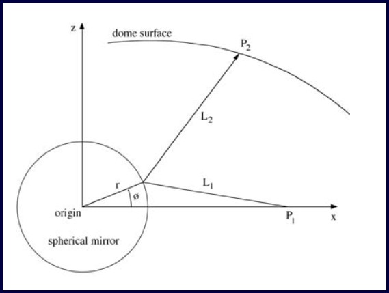
Figure 3. Geometry after the coordinate system has been transformed to place the spherical mirror at the origin and the intersection of the projected ray on the mirror/dome in the x-z plane.
For the image on the dome surface to look correct and undistorted, a precisely warped image needs to be projected. The form of the distortion can be seen in figure 4. Figure 4a is a regular polar grid appropriate for fisheye projection and figure 4b is the warped version that will look correct on the surface of the dome. Figure 5 shows the projector and mirror arrangement with a warped polar mesh on the computer display and the resulting image on the mirror.
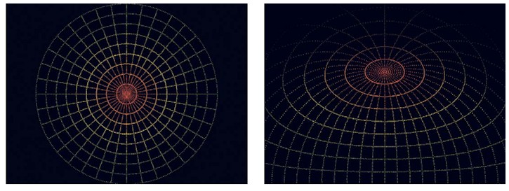
Figure 4. Warping of lines of longitude and latitude. The fisheye image in 4a consists of equally separated lines of longitude and latitude and is a convenient test pattern for dome projection. If 4b is correctly projected and viewed from the center of the dome, the central pole should be at the highest point in the dome, the lines of longitude and latitude should all appear vertical and horizontal respectively, and the line of 0 latitude should encircle the horizon of the dome. Note the intensity is varied so it fades gradually to back at the rear of the dome.
Creating correctly warped images given a particular projector, mirror, and dome arrangement requires finding the point on the projector frustum for any point on the dome. The problem is three-dimensional but can be turned into a simpler two dimensional problem by firstly translating the geometry so the spherical mirror is at the origin and then rotating the geometry so that the point on the mirror, dome, and projector lies in a single plane. In figure 3, the projector is located at P1, the mirror is of radius r, and the position on the dome is P2. The path length from the projector to the mirror is L1, the path length from the dome to the mirror is L2, these are given as a function of ø below:
L12 = (P1x – r cos(ø))2 + (r sin(ø))2
L22 = (P2x – r cos(ø))2 + (P2z – r sin(ø))2
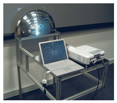
Figure 5. Projector and mirror in development configuration, the projected image on the laptop screen and mirror surface is a warped polar grid.
Fermat’s principle states that light travels by the shortest route, so ø can be found by minimising the total light path length from the projector to the position on the dome, namely minimising (L12 + L22)1/2. Once a relationship can be made between positions in the projection plane and the dome, a regular mesh can be created where each node is represented by normalised frustum coordinates
(x, y), fisheye image texture coordinates (u, v), and an intensity value. The intensity value can be used for compensating for the brightness variation due to the range of light path lengths, to softly fade the image towards the back of the dome, and to implement edge-blending
for multiple projector configurations. Figure 6 shows a fisheye image applied as a texture onto a regular mesh using OpenGL. Similarly, a standard approach to creating fisheye images in interactive OpenGL applications is to render four faces of a cube and form the fisheye image by applying those as textures on a mesh with precisely specified texture coordinates. Figure 7a shows the mesh onto which four cubic map textures are applied to form the correctly warped fisheye; figure 7b shows a resulting screen dump from a real time driving simulator.
It should be noted that while the discussion here has concentrated on hemispherical domes, it can also be employed in any situation where extremely wide angle projection is required. In particular, it could be used to wrap the output from a single projector into a rectangular room, achieving an undistorted result similarly requires the calculation of the correct warping function.
Conclusion
An alternative dome projection system has been designed and demonstrated to be suitable for small planetarium domes. The mathematics required and practical issues involved in warping fisheye images as a preprocessing stage and in real-time have been developed and tested. By comparison to the more conventional fisheye solutions, the spherical mirror solution suffers from no serious disadvantages and offers some advantages at a significantly lower cost. Future work includes creating an optimal mirror surface rather than using a spherical surface. Such an optimal surface will use all pixels in the rectangular image plane and attempt to distribute them equally on the hemisphere.
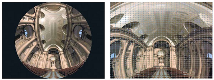
Figure 6. Fisheye image shown in 6a is applied as an OpenGL textured mesh in 6b. Each mesh node in 6b is represented by (x,y) coordinate
in normalized projection plane coordinates, a (u,v) texture coordinate that relates to the fisheye image, and an intensity
value that can compensate for the variable light path length.
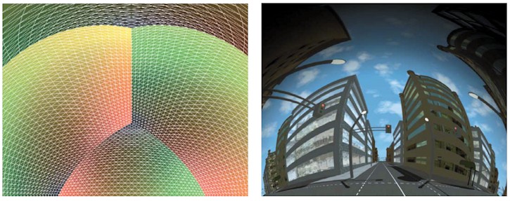
Figure 7. 7a shows the warped appearance of the four texture regions and mesh outline as used by real-time OpenGL applications.
The textures are derived from 4 virtual cameras each with the face of a cube as the projection plane. 7b is a single frame from a
real-time driving simulator using the warped texture meshes in 7a.
References
1. The History of the Planetarium, Chartrand, M.R., Planetarian, Vol 2, #3, September 1973.
2. Proceedings of the IPS 2004 Special Session Fulldome Standard Summit. Valencia, Spain, July 7/8, 2004.
3. Inflatable planetarium domes, Starlab Inc. [http://www.starlab.com]
4. Ensphered Vision, Hashimoto, W., Iwata, H., Ensphered Vision: Spherical immersive display using convex mirror. Transactions of the Virtual Reality Society of Japan , 4 (3) 497-486.
65 Bourke, December 2004. [http://astronomy.swin.edu.au/~pbourke/projection/dual dome]
6. Spherical mirror projection for an upright dome. Paul Bourke, May 2005. [http://astronomy.swin.edu.au/~pbourke/projection/uprightdome]


