Design guide for ETFE foil
Architen Landrell is an organisation with an international reputation at the forefront of tensile architecture innovation. They specialise in employing the principles of structural membrane design to create landmark buildings and iconic features that provide insightful, creative and cost-effective solutions to traditional construction and fit-out design briefs.
This is a brief guide for ETFE design For detailed information, please visit their website.
ETFE Foil: A Guide to Design
INTRODUCTION
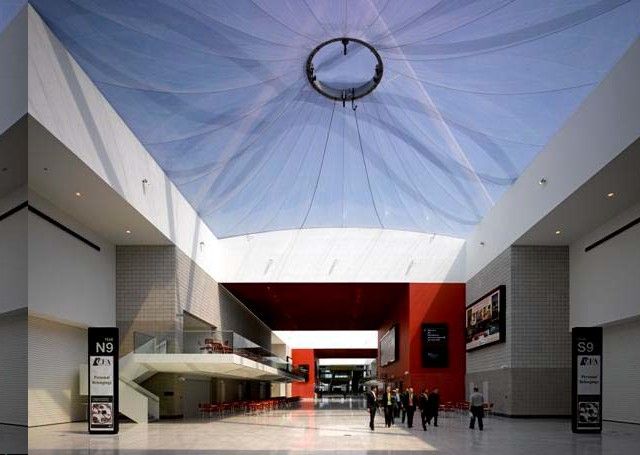
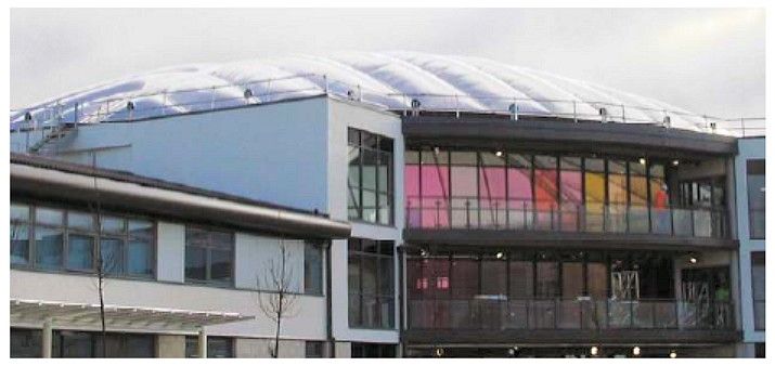
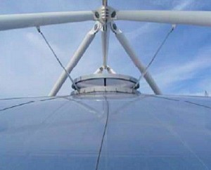
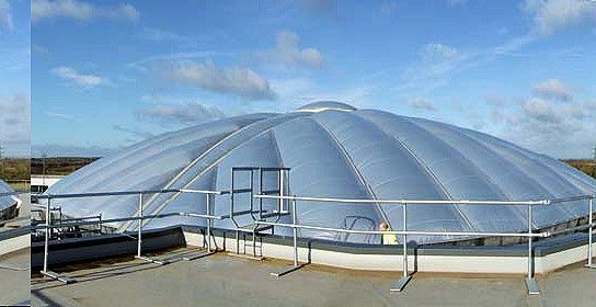
ETFE foil roofs can be supplied as a single layer membrane supported by a cable net system or commonly as a series of pneumatic cushions made up of between two and five layers of a modified copolymer called Ethylene Tetra Flouro Ethylene (ETFE). The ETFE copolymer is extruded into thin films (or foils) which are used to form either a single layer membrane or multi-layer cushions supported in an aluminium perimeter extrusion which, in turn, is supported by the main building frame.
In the case of ETFE cushions, they are kept continually pressurised by a small inflation unit which maintains the pressure at approx. 220 Pa and gives the foil a structural stability and the roof some insulation properties.
INSULATION
While a single ply ETFE membrane has an approximate U value of 5.6 w/m²K, a standard three layer cushion can achieve a U value of 1.96 w/m²K – a better insulation value than triple glazing when used horizontally (glazing manufacturers figures are for vertical glazing which considerably enhances the figures). The insulative qualities of ETFE cushions can also be improved by the addition of more layers of foil (up to five in total) or by treating the foil with specialist coatings to enhance the thermal properties.
 TRANSPARENCY
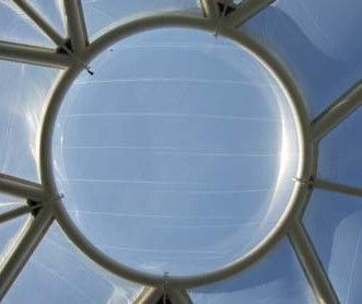
ETFE Foil is naturally a very transparent material and transmits light across the entire visible light region (380- 780nm). A single layer of medium weight ETFE has an approximate 85% light transmission, although multiple layers will lead to a small reduction.
Transmission across the ultraviolet range (320- 380nm) is also very good (approx 83-88%) and therefore allows plants and vegetation underneath to thrive. It is also important to note that the film absorbs a large proportion of infra red light transmitted, a quality which can be exploited to improve buildings energy consumption.
SOLAR CONTROL
As described above, the base material of an ETFE installation is very transparent, however, the ETFE Foil can be treated in a number of different ways to manipulate its light transmission properties. These include:
- Printing: Also known as fritting, the surface of the foil is covered with a variety of patterns to reduce solar gain while retaining translucency. By varying the percentage of coverage and density of the ink, the energy transmission can be altered. Alternatively, the foil can be over printed with a number of treatments to affect transmission. We offer a standard range of over 20 standard fritting patterns to achieve this variety of light transmissions, however, bespoke
patterns are available at an extra cost.
- Tinting: A selection of coloured foils are also available, although less readily than the standard clear foil. Coloured foils can be used alongside clear foil to incorporate branding and large scale imagery. White ETFE foil can be used to reduce glare but maintain some light transmission and insulation properties.
- Surface treatments: Surface treatments undertaken during the manufacturing process can vary the properties of the fabric and allow us to manipulate light transmission. These treatments render the foil matt in appearance and therefore provide an excellent projection surface for light shows and images.
- Radiation: The foil be conditioned with a range of radiation treatments which can reduce the
levels of IR and UV rays transmitting through the membrane skin.
Adding additional layers of ETFE foil to a cushion also allows light transmission and solar gain to be controlled. Multi-layer cushions can be constructed to incorporate movable layers and intelligent (offset) printing. By alternatively pressurising individual chambers within the cushion, we can achieve maximum shading or reduced shading as and when required. Essentially this means that it is possible to create a building skin which is reactive to the environment through changes in climate.
G VALUE
The G value of an installation reflects the fraction of solar energy transmittance through glazing. This is usually expressed as a percentage or a value between 0 & 1; the higher the number, the more energy is being transmitted through the glazing and the more the building will heat up.
The G value of an ETFE roof can be reduced to as little as 0.48 for a 2 layer system with a fritted top surface and to around 0.35 by using a 3 layer system. For comparison, standard glass is approx 0.88 whereas some specially treated glass may be as low as 0.46.
It must be noted that the G value of any ETFE installation is very dependant on aspect and location and should be calculated on a project by project basis taking these elements into account.
LIFE
 ETFE Foil has an excellent life expectancy as it is unaffected by UV light, atmospheric pollution and other forms of environmental weathering.
While no ETFE structures have been in place for long enough to gain a true understanding of the life cycle of the foil, the material has been extensively researched and tested in a laboratory environment and out in the field. These tests have concluded that no degradation or loss of strength has occurred and there is no sign that the material will become brittle or discolour over time. As a result, it is anticipated that the material has a life expectancy in excess of 50 years.
FRAGILITY
ETFE foil cushion systems are certified as class C non fragile roof assembly in accordance with ACR(M)001:200 – test for fragility of roofing assemblies.
Class C is the lowest class of non-fragile assembly and, particularly if engineered to pass the test criteria, may be close to the boundary between fragile and non-fragile. Its classification and use therefore requires the following to be taken into account:
a) Normal industry-recommended best practice is that Class ‘C’ assemblies should never intentionally be walked upon and appropriate temporary access equipment, such as crawling boards, etc., should always be used. Note: Accidental damage to such assemblies might render the classification void.
b) A Class C assembly must be treated like any other safety critical item, e.g., a safety net. Therefore, any adverse occurrence that could affect its fitness for purpose should trigger an inspection. If an assembly has been subjected to an impact load (such as a trip or stumble), it can be treated as a fragile area and identified and protected accordingly, until it has been replaced and the adjoining fitted panels inspected by a competent person and replaced if necessary. Procedures to ensure this happens must be in place.
c) The workforce must be aware of these limitations, as required by Regulations 3 and 8 of the Managing Health and Safety at Work Regulations [MHSWR].
d) Any person falling on a class C assembly may make it fragile for subsequent loads. While persons may be capable of self-recovery from a fall or stumble, where they are unable to, the additional weight of a rescuer may cause the assembly to fail. And, because all non-fragility classifications depend on the fixings of assemblies, any adjoining assemblies may also have become fragile. In such situations the incident panel and all adjoining panels must be treated as fragile. This is a foreseeable risk of selecting Class C assemblies. Therefore, where class C assemblies are being used, rescue plans must be developed in advance of work starting.
INFLATION UNITS
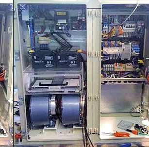 ETFE cushion systems are continually inflated by air handling units from which air pipes run to each individual cushion. As the cushions only need to maintain pressure and not generate air flow, the energy consumption used by these units is minimal. An entire roof is generally powered by a single air handling unit which contains 2
fans powered by electric motors. For large installations there is sometimes a need for additional air handling units to be installed.
The fans run alternately to maintain pressure within the cushions, with only one fan running at any given time. In the event of a cushion failure, adverse weather conditions or a drop in cushion pressure, both fans will run simultaneously to maintain a steady pressure.
 If required the inflation units are also fitted with dehumidifiers to dry the air being fed into the cushions.
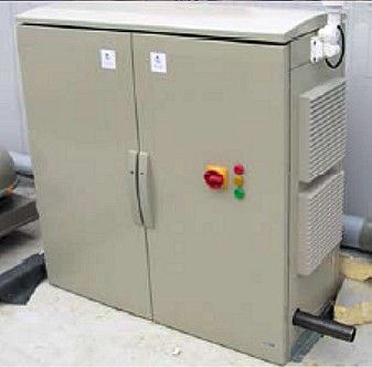
A typical air inflation unit measures 1.2m x 1.2m x 0.9m and is located near to the ETFE cushion system, internally or externally. The system requires a dedicated and secure power supply consisting of two 240V 13 amp electrical connections – as the ETFE foil roof is a live system the cushions are permanently linked to the air inflation unit to ensure the pressure is maintained.
CONTROL SYSTEM
As standard our ETFE cushion roofs are supplied with a state-of-the-art active monitoring system. This continually supplies real-time information on the pressure within the cushions, the local weather conditions, temperature and humidity levels and any faults or changes within the operation of the system to a local LCD screen – see fig. 1. It is possible for Architen Landrell (or a designated user) to gain access to the control system remotely which assists with off-site updates or diagnostics in aid of fault finding and can allow minor pressure and performance adjustments.
Continual monitoring allows the system to automatically adapt to avoid potential problems. In the event of a problem the control system will automatically try to compensate for the fault; for example, when a drop in pressure occurs the rate of airflow to the cushions will increase automatically. In addition, the fault is logged and displayed on the main controller and relevant air handling unit (using the traffic light system described below) and an automatic alarm notification can also be sent to a predefined person. The alarm will be raised as soon as a fault is registered.
To allow simple diagnostics, maintenance staff can inspect the coloured indicators “traffic lights” on the front of the air handling unit. The traffic lights display the status of the inflation equipment:
- Green light – all working fine
- Green & amber lights – minor problem, needs attention (for example, a partially blocked air filter)
- Red – Immediate attention required
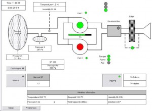
Fig. 1 – Example of Architen Landrell’s state-of-the-art monitoring and control system. Click to enlarge.
POWER FAILURE
In the unlikely case of a power failure, the ETFE cushion system will maintain pressure for between 3 and 6 hours before deflating (dependant on weather conditions). This is due to the non-return values built into the air inflation units. After this time, there is a possibility that, as pressure drops, the roof will become damaged. As a result we recommend that there is either a standby generator or alternatively a cable bracing system installed to support the cushions should this situation arise. Aside from this, we always recommend that the roof is closely monitored to avoid predictable problems occurring.
SAFETY/EXPLOSION RISK
As a flexible material, ETFE Foil can take very high loadings for a short period of time which makes it an ideal material for use in locations where there is a risk of explosion. If vandalism is a threat, ETFE foil is also an advantage as the cushions will not break or fall from the extrusion frames if damaged.
REPAIR AND REPLACEMENT
One of the outstanding characteristics of EFTE foil is its exceptional tear resistance, lack of notch weakness and stress crack concentration. Any cuts and scratches initially propagate but the material rapidly stretches and rounds out into a tough low radius area that dissipates the loads and prevents further tearing.
Minor repairs to the foil, such as a puncture hole, can be carried out in situ and within a relatively short timescale by using an adhesive ETFE foil patch. Fritted material would be used to match existing fritted foil in order that repairs do not affect the aesthetics of the structure.
If an ETFE Foil cushion becomes more significantly damaged, an individual cushion can be easily removed and replaced with minimal disruption to the installation as a whole. The outside surface of the ETFE cushion can be accessed by technicians, using rope access techniques, from the main structural steel support. This would require the rigging of working ropes from the steel and is routinely done under the IRATA guidelines.
Should a problem occur with the control system, every effort will be made to diagnose the problem remotely. Once the problem is identified, it can be fixed in one of two ways:
1. Remote repair (software problems)
2. On site (hardware problems). If on site repair is required, we will only need access to the building control room to resolve the problem.
BIRDS
The most common threat of tearing or damage is from birds; excessive bird pecking can cause small punctures in the ETFE cushions. In general this poses no threat to the stability of the cushion as a whole as our system is supplied with built in active monitoring which will automatically adjust to compensate for the slight drop in pressure. As a precaution, all Architen Landrell structures are supplied with bird wire deterrent to stop bird perching on the extrusion/steelwork.
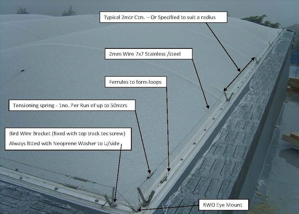
Click to enlarge
FIRE
 ETFE Foil as a material has low flammability (270C) and is considered self extinguishing. In the event of a fire, hot smoke will cause the foil to soften, fail and then shrink away from the fire source to create natural ventilation. The quantity of material used in the roof is not important in this situation – the foil will not create molten drips or any fumes.
ETFE foil has been comprehensively tested. This is a selection of the fire results:
DIN 4102 Class B1
EN 13501-1 Class B-s1,d0
NFP 92-505 M2
NFPA 701 Pass
For more information on specific fire tests, please contact Architen Landrell. In some cases, it is not possible to guarantee that smoke will reach the ETFE at a temperature which will cause the cushions to fail, therefore, it is worth considering the installation of automatic actuators in order to ventilate the space of smoke.
ACOUSTICS
ETFE foil cushions are a relatively transparent form of roofing which means that there are minimal acoustic benefits in it’s natural state.
Rain noise can be suppressed using a rain attenuation layer added to the top surface of the cushions. This acts as a dampener, stopping the sound reverberating around the space below. In general, the installation of a rain attenuation layer is only necessary in exceptional circumstances. This can be retro fitted to the ETFE foil cushion system and therefore we recommend that rain noise is assessed prior to making a decision to install.
ENVIRONMENTAL
The raw material associated with ETFE is a class II substance admitted under the Montréal treaty. Unlike its class I counterparts it causes minimal damage to the ozone layer, as is the case for all materials used in the manufacturing process. The production of ETFE involves the transformation of the monomer TFE in to the polymer ETFE using polymerisation; no solvents are used in this water based procedure. The material is then extruded to varying thicknesses depending on application; a process which uses minimal energy. Fabrication of the foil involves welding large sheets of the ETFE; this is relatively quick and again a low energy consumer.
 ETFE can be recycled with ease, but due to its properties (does not degrade under UV light, sunlight, weather, pollution) it has a very long life which is estimated between 50-100 years, making the need for recycling small. Excess material from the cushion manufacturing process can be recycled effectively by all ETFE suppliers. The aluminium frames do require a high level of energy for production, but they also have a long life and are readily recycled when they reach their end of life.
ETFE cushion systems offer both good insulation and translucency, due to the fact they trap a layer of air and can be adapted using dot matrix coatings to change the solar transmission. The weight and size of the EFTE has added benefits making it much more energy efficient than materials with the same desired architectural effect. For example, transportation of the material is much easier as it can be rolled, taking up less space, hence the need for less conveyance. The cleaning and maintenance of ETFE is also small, the majority of the time water will wash off any dirt, this is due to the smoothness and anti adhesive properties of the material. If cleaning is needed then only light PH neutral detergents are used making the environmental impact minimal.
RAINWATER & DRAINAGE
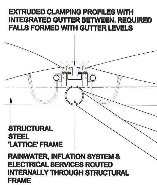
Fig 2. Gutter Detail
All ETFE structures are designed with curvature to ensure that rainwater does not ‘pond’ or collate on the top of the membrane as this leads to deformation of the foil. Rainwater will be channelled to the perimeter of the roof where it can be collected in the main gutter system. Gutters are not supplied as standard within most ETFE installations but they can be incorporated if required. See fig.2 – Gutter Detail.
CLEANING
Unlike traditional fabric structures, ETFE Foil is an extruded material and therefore has a smooth surface. This smoothness reduces the amount of dirt retained on the ETFE foil surface and allows the rain to wash away the majority of bird droppings etc. As a result, we advise that ETFE foil cushions are cleaned externally every 2-3 years.
The cushions themselves also need to be cleaned internally, although far less often. Depending on the amount of dirt collected in the internal atmosphere, we would recommend they are cleaned every 5-10 years on the interior surface of the cushions.
We recommend that the inflation units are serviced every year, however, an active monitoring system is incorporated in all our units which supplies continual information on performance.
If a rain attenuation layer has been installed the frequency of cleaning required may be increased but this will vary from site to site.
Architen Landrell has a designated Maintenance Department which deals with planned and emergency works at sites across the world. Our maintenance personnel are based at our office in Chepstow and have a fleet of vehicles available for site visits. In the event of an emergency, we also have a 24/7 dedicated telephone line for call outs and advice.
WEIGHT
ETFE Foil cushions are extremely light weight weighing only 2 – 3.5 kg/m².
CUSHION SIZE
ETFE foil cushions can be manufactured to any size and to fit any shape. Size is limited by the wind and snow loading allowed for within the design and by the orientation of the cushions i.e. whether they are installed horizontally or vertically.
As a general design guideline, rectangular cushions can span up to 3.5m in one direction and as long as required in the other direction. For triangular cushions, the size can be greater than this. If design dictates that larger cushions are required, these can be created by reinforcing the internal and external layers of the cushion by cable restraints.
WARRANTIES
Warranty is available for all our ETFE foil cushion systems. We recommend that a maintenance agreement is also undertaken to ensure the foil and air inflation equipment are in full working order.
MATERIAL STRENGTH
Based on 250 micron ETFE Foil
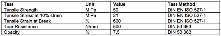
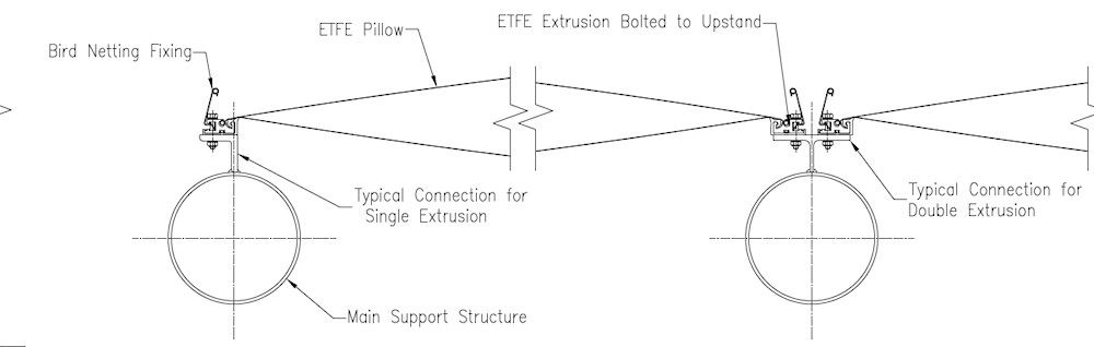
Fig.3 – Typical section through an ETFE cushion. Click to enlarge
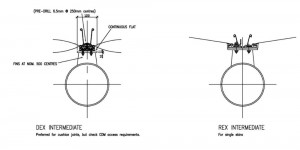
Fig.4A – Architen Landrell Extrusions. Click to enlarge
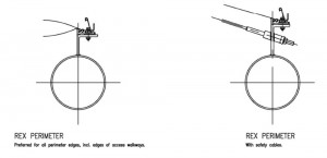
Fig.4B. Click to enlarge.
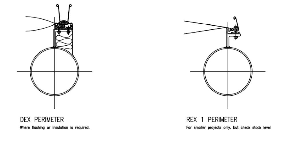
Fig.4C. Click to enlarge.
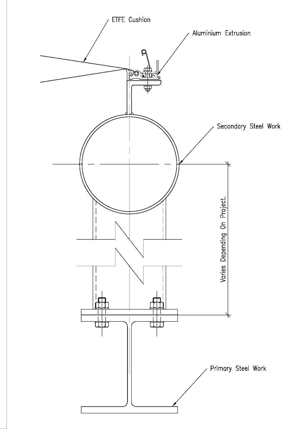
Fig.5 – Perimeter steel connection detail. Click to enlarge

