Building with foil cushions
Foil cushions – creating building envelopes!
Summary
Foil cushions that consist of thin ETFE membranes that are pneumatically pre-stressed to provide cladding for structures. Wide spans can be achieved thus allowing large spaces to be designed. The material’s extremely low dead weight combined with it’s high strength allows for infinite variations of the contours. ETFE cushions reduce the overall load on a supporting structure allowing for optimization of the members.
Foil cushions: shell of buildings!
Abstract
Foil cushions – pneumatically pre–stressed thin membrane structures made of ETFE – are used in buildings as claddings with thermal properties. Due to the air buffer between various layers, foil cushions achieve very satisfying insulation properties and are used as wall or roof cover. In comparison to structural glazing, foil cushions allow larger spans in almost any shape and large transparent areas. To take advantage of the unique properties of ETFE foil cladding, examples of special and highly optimized structures are presented.
1. Introduction
The works of Frei Otto and the construction of Munich’s Olympic Stadium laid the foundations for building with membranes in Germany and helped to launch a development that is far from being over. It relies on the principle of counteracting curvatures and anticlastic constructions to pretension the membranes and define the shapes. A single layered fabric cladding, offering protection against the elements, is usually mechanically pre-tensioned. Successful attempts were made during the early 1980s to use membranes in the form of pneumatically stabilized cushions made from ETFE plastic foil (Texlon® brand).
The emphasis of this paper is not single layered membranes but ETFE foil cushions consisting of two or more layers forming the envelope. In addition to providing protection against the weather, ETFE cushions also offer good thermal insulating properties. ETFE (ethylene tetrafluorethylene) is obtained from fluorspar and is ideally suited for this purpose. ETFE has transformed the architectural industry in the past 30 years and many iconic and prestigious buildings have benefited from this technology.
2 . The ETFE material
ETFE has the following properties:
• Tensile strength > 50 N/mm²
• Elongation at break > 350% according to DIN EN ISO 527-1
• Tearing resistance > 400 N/mm according to DIN 53363
• Cold temperature resistance of -160°C
• High light transmission including UV radiation
• UV stable and aging/weathering resistant
• Anti-adhesive smooth surface (self-cleaning)
• Resistant to hail according to SlA V280 and EN 13583
• Young’s Modulus of approximately 700 N/mm²
• Fire class B1, non-burning drip from 250°C
• Suitable for welding
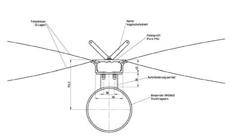
Figure 1.
ETFE foils have been exposed to both natural and artificial weathering conditions for more than 30 years without suffering any substantial changes. In these tests the ETFE foils were exposed to extraordinarily high air pollution and UV radiation levels. No decomposition or deterioration of the foil’s properties were measured. The material is inherently UV stable and transparent to UV radiation thus requiring no additional chemical additives. ETFE is fully recyclable and can be reintroduced to the production process after the end of their previous design life. Texlon® foil systems have proven themselves to be self-cleaning due to anti-adhesive surface: even persistent dirt like bird droppings are washed by rainfall.
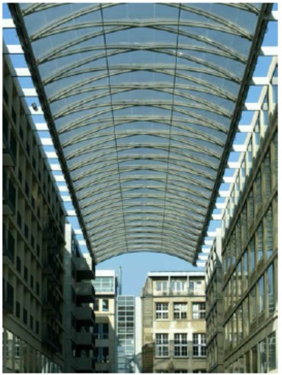
Figure 2. DomAquareé – Berlin, DE
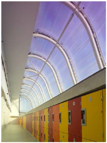
Figure 3. Kensington Academy – Liverpool, GB
3. Technology
The pneumatic pre-tensioning with a low pressure air system gives the cushions a stable shape and prevents the foils from billowing and fluttering in wind conditions. The cushions are fixed by means of a continuous keder piping connected to a lightweight extrusion (Figure 1). The extrusion is bolted to the supporting structure to provide a frame onto which the cushion is mounted.
Figures 4 & 5.
These cushions can be patterned into virtually any shape, for example the triangular and diamond shaped cushions on the Dom Aquarée roof (Figure 2), or cushions curving over the eaves of the Kensington Academy (Figure 3). Rolls of foil, ranging from 100 microns to 250 microns, are cut to the desired shape and are welded together to form cushions.
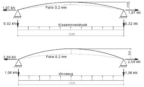
ETFE cushions are analysed using the membrane theory. Using this analysis method the optimal span for the cushions can be assessed. Long flat cushions with a ratio of Iength to width l/w > 2 are spanning over the short span. They can be calculated using a simplified two-dimensional analysis method. Three-dimensional considerations according to the finite element method are required to give more accurate results in view of the load-bearing behavior of the cushions.
The cushions are made to suit the exact dimensions of the contour. They are patterned to allow for an initial rise and dip between the upper and lower foils. After installation they are subjected to an internal pressure of typically 200 Pa, which pre-stresses and elongates the foils to give the cushions their basic shape.
When short term loads are applied to the cushion one of the foil layers is further stressed, whereas the opposite foil is ‘relaxed’ in a way that is similar to a cross bracing consisting of pre-tensioned cables. If the short term loading applied exceeds the amount of the internal pressure by a factor of two, then only one of the foil layers is supporting this loading. In the case of long and medium term loadings, e.g., snow, it must be assumed that air will gradually be pushed out of the cushions when the load exceeds the internal pressure because the cushion is not a closed system. In such a case the foils would lie directly on top of each other and contribute to supporting the loading. The water ponding from melted snow or rain need to be considered in view of the geometry and slope of the cushions. In cases where water ponding, snow or large wind loads over stress the cushions (e.g., peripheral suction peaks) it may be necessary to support the ETFE cushions by means of thin steel cables.
Water ponding can be caused by melting snow in combination with additional rainfall. A malfunction of the inflation unit can also be a cause for rainwater collection eg. water ponding in the unpressurized cushions. The water ponding case is only a short-term loading condition if the analysis considers all risk circumstances correctly. The cushion’s shape will recover and the collected water will eventually drain off when the pressure-supply is restored. It is recommended to incorporate a slope for the cushions to avoid or significantly reduce water ponding issues. Valves forcing the drainage of the cushions can also be installed in some cases. It is, however, not recommended above closed spaces. The reliability of these valves may be adversely affected by leaves, ice or other debris.
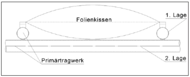
Figure 6.
The roof spanning the internal courtyard of the DomAquarée (Figure 2) is a typical example showing the non-linear behavior of ETFE foils. The load-bearing capacity of the foil increases over proportionally when the spacing between upper and lower layers is increased. The resulting horizontal force at the perimeter increases under proportionally.
The extrusions and the supporting structure must be designed to be able to resist the forces that are imposed vertically on the cushion’s axis, as well as for the horizontal forces arising from the cushions and cables. The reaction forces are calculated for the specific geometry and curvature including the resulting deflections. The internal pressure generates horizontal reaction forces that are to be applied permanently. Additional loads will increase the horizontal reaction forces. In general rule horizontal forces from neighboring cushions cancel each other out, so that only
the frames that are at the perimeter are required to take into account the tensile forces to their full effect.
It is necessary to examine the event of an Inflation unit malfunction whereby one or several cushions are in an unpressurized state (e.g. if the foil is damaged by a hurricane) when considering the structural stability. This scenario must be considered when designing the supporting structure. The resistance of the supporting structure is paramount for the structural stability of the entire building. Due to the strength of ETFE in combination with its yielding behaviour (increase of gap causes an increased load bearing capacity) the supporting structure may need to have additional capacities to allow for this scenario.
It may be advisable to increase the inflation pressure in certain instances where it is necessary to prevent the cushions from collapsing under applied loads by means of increased pneumatic pre-tensioning. This system generally requires more material, higher operating costs and makes increased demands on the controlling system and air tightness of the system. The aforementioned inflation unit malfunction must still be addressed.
4. Optimized constructions
Using currently available foil thicknesses, cushions spanning up to 4.0m wide, depending on certain parameter and situations, are possible without the need for reinforcement cables. The length of the cushions is practically unlimited. As opposed to glass, curvatures, deformations and warpages are easily achieved with ETFE cushion systems.
The degree of curvature is limited to a certain extent for geometrical reasons, however, this limitation has no effect on buildability. Square, polygonal or round cushions with biaxial stress distribution allow larger spans. Even for these forms, it would be advisable to incorporate a slight slope in the arrangement of the cushions.
The design of the supporting structure must be coordinated with the cushion design. It is often beneficial to arrange the primary structure using crossing members that lie in two layers (Figure 6). This arrangement allows for the air gap to be accommodated without touching the structure. Since the structural tubes are not lying in the same plane, simple connections can be designed. The eccentric horizontal forces from the cushion do not significantly affect the connection design.
The flexibility of the ETFE cushions and the possibility of variable welded seams enable the cushions to be made to measure for almost any shape. This allows for a vast scope for creative design. It is possible to install ETFE cushions on “soft” supporting structures like cable net structures offering watertight building envelopes that allow movement in the structure.
Figure 7. South Glouceser-Council Offices – South Gloucester, GB
Figure 8. Detail: South Gloucester-Council Ofices – South Gloucester, GB
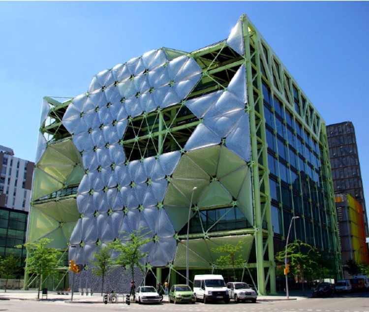
Figure 9. MediaTIC – Barcelona, ES
5. Examples
South Gloucester-Council Offices, GB (Figures 7 + 8)
Area: 474 m²
Year of construction: 2009
Steel supporting structure
Media TIC in Barcelona, ES (Figure 9)
Aera: 2.304 m2
Year of construction: 2009
Steel supporting structure
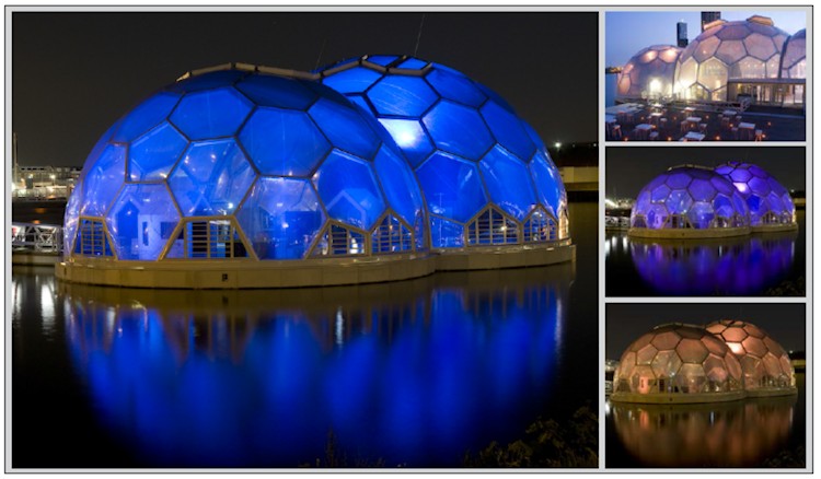
Exhibition Pavillion in Rotterdam, NL (Figure 10)
Area: 1.330 m²
Year of construction: 2010
6. Applications
Texlon® foil systems are mainly utilized for transparent roofs and facades in architecturally challenging buildings. The transmittance of ultra-violet light also makes them ideal for private and public swimming pools as well as in zoological and botanical gardens.
The light transmission can be intelligently controlled by printing patterns onto the foils or by adding pigments to color the foil. The combination of several layers of foil, staggered printing and pneumatic controls allow shading to be adjusted in a selective manner.
Advantages Compared With Structural Glass Technology
• The system’s low weight (particularly advantageous for refurbishment projects)
• Wider spans result in a larger transparent/translucent spaces
• Flexible 3D shaping
• Deformation is not an issue and therefore ideally suited for cable structures
• Large range of coloring and graphic printing available
• Lower cleaning costs
• Excellent UV transmission
• Very good spatial acoustics with short reverberation times
• Light weight supporting structure options possible
Disadvantages
• Poor acoustic insulation
• Maintenance of the inflation units
U values ranging from 2.94 W/m²K for a two-layered cushion to 1.18 W/m²K for a five-layered cushion are achieved. Translucent, pigmented foils (frosted glass effect) and even LED media facades which are capable of displaying videos (Texlon® flexipix) are particularly suitable for modern luminous architecture. The thermal insulating properties of the clamping profiles have also been greatly improved.
7 Conclusions
Foil cushions made from ETFE have been used successfully as thermally insulating building envelopes for almost 30 years. They enable large transparent or translucent areas to be created with an extremely low degree of shading from frames and supporting structures.
The flexibility of the ETFE cushions and the possibility of variable welded seams enable the cushions to be made to measure for almost any shape. Long rows of cushions that are slightly sloped longitudinally or transversely with a width of up to approximately 4 m, in conjunction with an adequate supporting structure are recommended. This design concept has been extensively applied for over 30 years and allows for economically beneficial building envelopes. Buildings that can be filled with natural light and that are a tribute to architectural expressiveness.
Dr.-Ing. Stefan Lehnert
Managing Director of Vector Foiltec GmbH
Steinacker 3, 28717 Bremen
de@vector-foiltec.com
Dr.-Ing. Tobias Schween
Ingenieurgemeinschaft Thor – Schipper – Schween
Neuer Markt 4, 49393 Lohne
info@tss-ingenieure.de

